The Friendly Virtual Radio Interferometer
The Friendly Virtual Radio Interferometer (VRI) is designed to simulate astronomical observations using linked arrays of radio antennas in a technique called earth rotation aperture synthesis. As the successor to the original Java-based VRI, it focuses on simulating the effect of combining different antenna layouts.


Installation:
Click on the ‘View on GitHub’ link at the top of the page and then the
‘Clone or download’ button to fetch the package code. The Friendly VRI
is written in Python to work with both Python 2.7.x and 3.x. The
recommended way to install is via an Anaconda environment. Run the following command to create an environment called vri:
conda env create -f environment.yml.
Once all required modules are installed, activate the environment:
conda activate vri
Usage
Start the application by executing python vriTk.py on the
command line from within the friendlyVRI/ directory. The
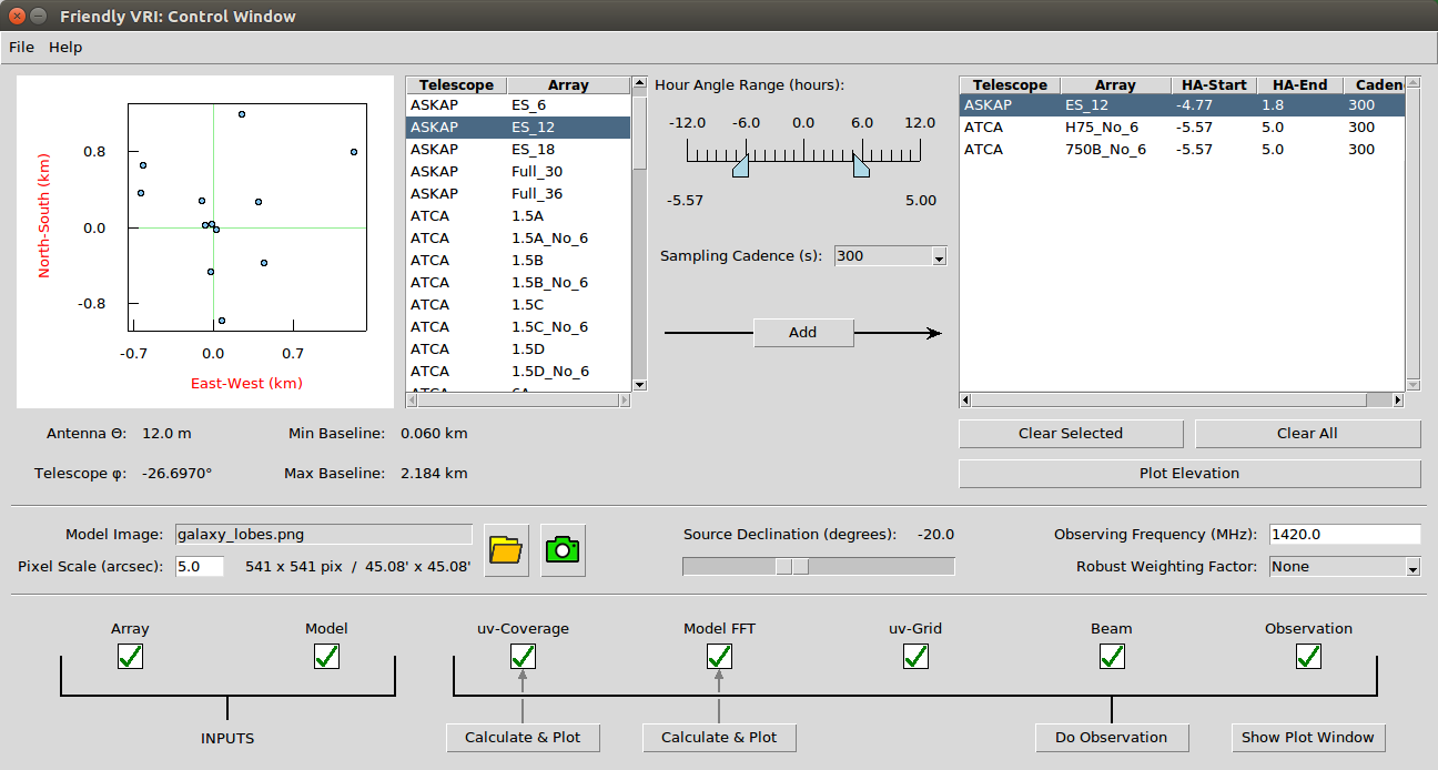
interface is (hopefully) very intuitive and is split into a control
window and a plotting window. The plotting window can be maximised and
buttons at the lower-right enable jumping quickly between the two
windows. The control window allows you to:
- Plot the layout of the antennas in an array configuration for a particular telescope.
- Create a list of observations to be simulated using different array configurations, over different time ranges (hour angle) and with different sampling cadence.
- Load in a model image and set its angular scale on the sky.
- Apply the uv-coverage of the observations to the model to simulate an observation.
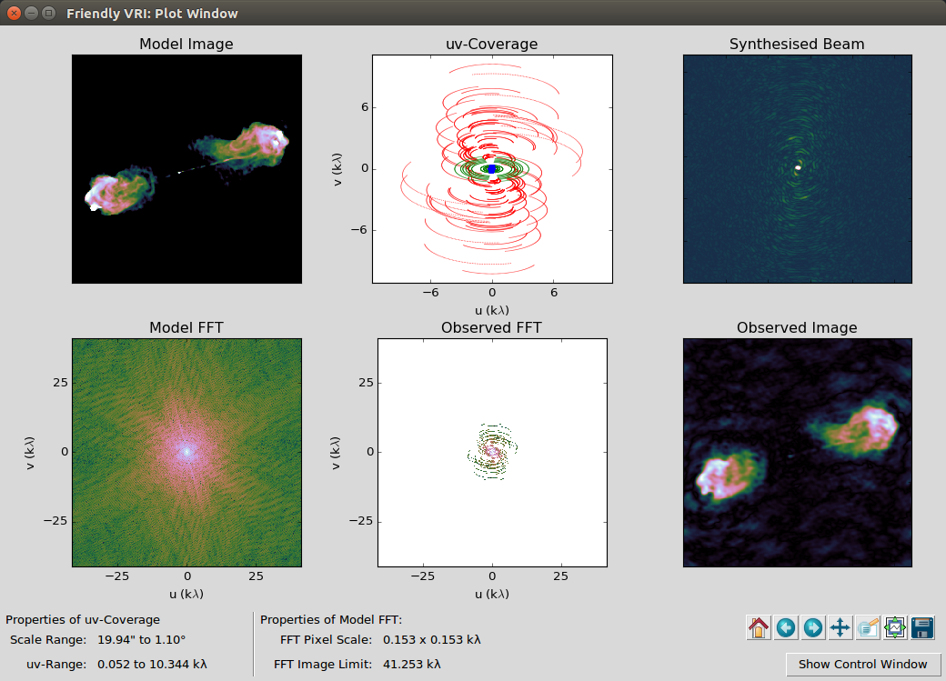
The plotting window shows inputs, outputs and intermediate steps in the process: model image, fast Fourier transform (FFT) of the model, plot of uv-coverage, filtered model FFT, synthesised beam and final observed image.
See HELP or the help menu in the application for step-by-step instructions.
Note that the calculations underlying the graphical application are
split into the file vriCalc.py to facilitate use with
alternative interfaces. See CALCULATIONS for a
simple example.
Defining Custom Arrays
The location and layout of antennas in each array configuration is
defined in ASCII files under the arrays/ directory. You can
define your own arrays by copying the existing templates and supplying
a list of coordinate offsets in the East and North directions, in units
of meters. The software will read these on start-up and they will
appear in the list of available arrays. Note that the combination of
‘telescope’ + ‘array’ name must be unique.
Caveats
This software is designed to be a simple ‘quick-look’ tool and ignores lots of effects such as non-co-planar arrays, time averaging, multi-frequency synthesis etc. It also sets the sampling grid in the Fourier domain from the extent and pixel spacing of the input image, which can result in under-sampled synthesised beams and artefacts. At the moment, the observing simulations are assumed to be noise-free and no attempt is made at calculating sensitivities. Tasks to perform robust simulations of an interfometric observation exist in CASA, MIRIAD and AIPS, but are more difficult to use.
Other VRI Software
Other excellent virtual interfeometer software has been developed by staff at observatories around the world:
- APSYNSIM is a ‘full-fat’ simulator by Ivan Marti-Vidal at Onsala Space Observatory, Sweden.
- Pynterferometer is a public demonstration tool by Adam Avison and Sam George and has excellent documentation in the accompanying paper.
Credits and Contact Information:
The Friendly Virtual Radio Interferometer tool was written by Cormac Purcell and Roy Truelove at Macquarie University, Sydney. Questions, comments, feature requests and bug reports should be directed to ‘cormac.purcell (at) mq.edu.au’.
Licence
Copyright (c) 2017 - 2022 Cormac R. Purcell and Roy Truelove.
Released under the MIT licence.